Convex Lens Ray Diagrams: How to Draw and Read Them
Learn the three principal rays for a convex lens and use their intersection to predict image position, size and orientation.
Quick answer
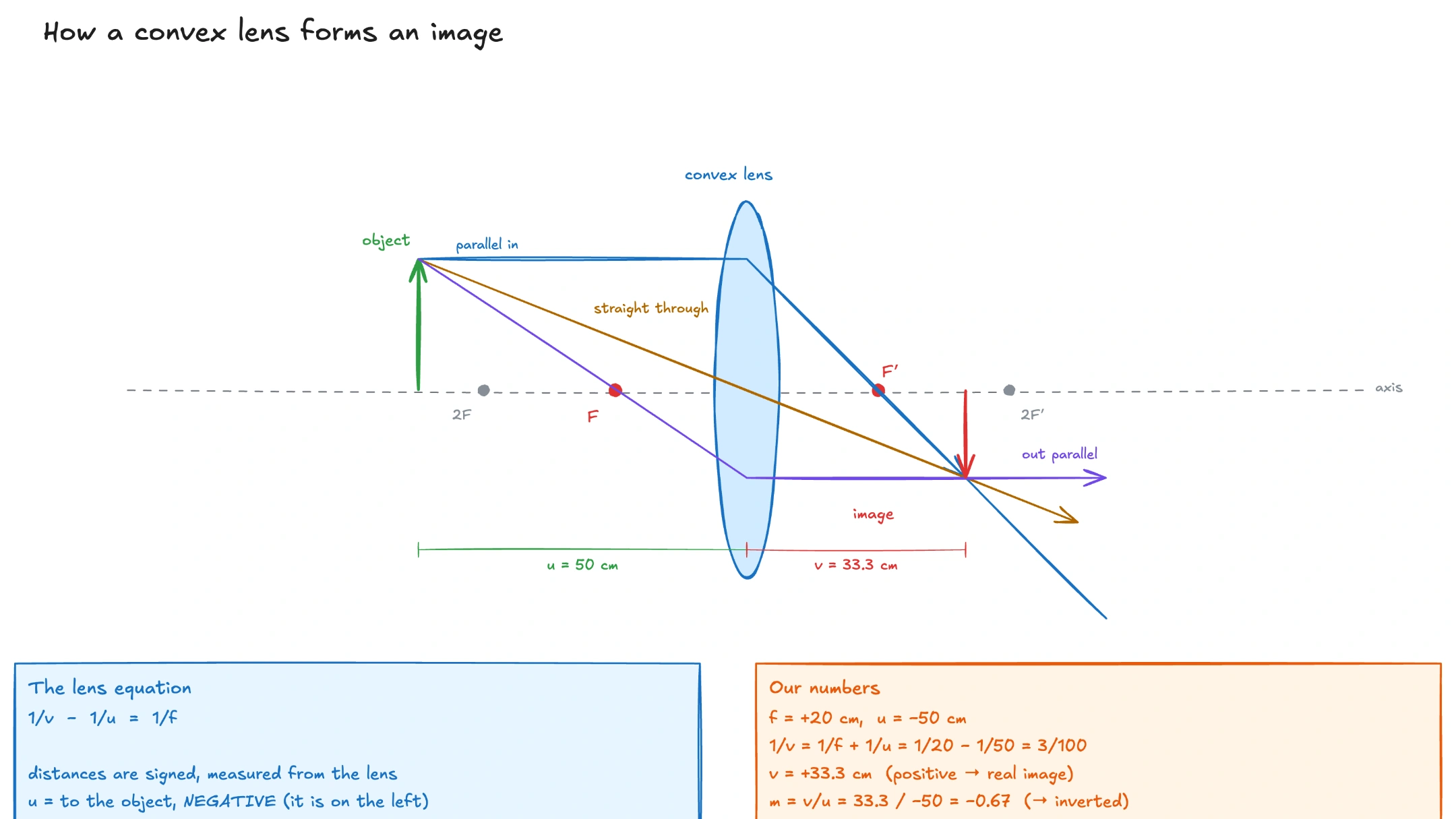
To draw a convex-lens ray diagram, place the object and focal points first. Draw at least two principal rays from the top of the object: a ray parallel to the axis refracts through the far focus, and a ray through the optical center continues approximately straight. Their intersection locates the image.
Key relationships
Set up the diagram before drawing rays
Draw the principal axis as a horizontal line and the lens as a vertical line through its optical center. Mark focal points F at equal distances on both sides. Place the object as an upright arrow with its base on the axis.
Accuracy matters more than decoration. If the focal points or object height are inconsistent, the principal rays will not meet cleanly and the predicted image will be misleading.
Use the principal rays
The parallel ray travels from the object tip parallel to the principal axis and refracts through the focal point on the far side. The center ray passes through the optical center and continues approximately undeviated in the thin-lens model. A third check ray can travel through the near focal point and emerge parallel to the axis.
Where the refracted rays meet is the image tip. Drop a vertical line to the axis to complete the image. If the real rays diverge, extend them backward with dashed lines; the backward extensions locate a virtual image.
Read what the picture is telling you
An object beyond twice the focal length forms a smaller, inverted real image between F and 2F. At 2F, object and image have equal size. Between F and 2F, the real image is inverted and magnified beyond 2F. Inside F, the image is virtual, upright and magnified on the object's side.
The thin-lens equation confirms the construction numerically. The sign and magnitude of magnification describe orientation and relative size.
What to remember
- The ray diagram predicts where the image forms and whether it is real or virtual.
- Two accurately drawn principal rays are normally enough.
- A real image forms where refracted rays actually meet.
- An object inside the focal length produces an upright, magnified virtual image.
Frequently asked questions
How many rays are needed for a lens diagram?
Two principal rays are enough to locate the image; a third ray is useful as a consistency check.
Why does the center ray go straight?
For a thin lens, the two small refractions near the optical center are modeled as having no meaningful net deviation.
How can I identify a virtual image?
The outgoing rays do not actually meet. Their backward extensions intersect on the object's side of the lens.
Watch a convex-lens ray diagram get constructed
Play the complete lesson free—drawn and narrated from start to finish, with no account needed.